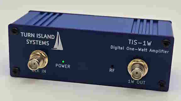
Turn your logic-level outputs into slightly more powerful signals! This design is one I have been using in the WSPRSONDE, and I’ve found it to be so useful that I put it in a little box along with a USB C power connection and a couple of indicator LEDs.
This will require a low-pass filter to convert the square wave output to a spectrally-pure-meets-all-FCC-regulations signal, but that’s pretty simple. This design easily covers all the ham bands between 160 and 6 meters.
Equipment using this amplifier circuit has been continuously transmitting for several years, from the steamy jungles of Costa Rica to the frozen wastes of the Arctic and Antarctic, The design and performance is thoroughly described in the product guide.
We’ve seen that that the small computers used in wsprsonde (and other) receive installations will reset or hang up during power outages, even when there is a UPS between the utility power and the computer’s power brick. It turns out that many UPS units have a momentary dropout when they transition to backup mode, and the brick power supplies do not have enough internal storage to ride through this transition. This is bad enough in home operation, but especially problematic in a remote installation with limited access.
There are certainly glitchless UPS products available (“on-line” UPS), but these are more expensive and sometimes “glitchless” really isn’t.
The TIS-1250 provides an alternative solution, by using a “supercapacitor” (1.25 Farads) and low-loss charging / discharging circuitry.
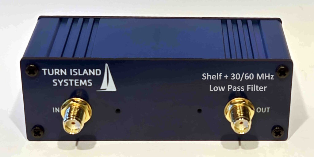
This is a new filter, designed for use with preamplified “probe” antennas, and many other receive antenna systems. This includes a bypassable low-frequency shelf filter, and can be jumper-configured for either 30 or 60 MHz low-pass anti-alias filtering.
This one has an aggressive low-pass filter, optimized to eliminate 88-108 MHz FM broadcast band signals before they can cause trouble. The high dynamic range preamp provides about +20 dB of low-noise gain.
Here is an opportunity to help in the exciting field of ionospheric propagation and other “space weather” research, by hosting a WSPRSONDE system provided by the HamSCI organization. HamSci is looking for a few good sites in North America for these WSPR / FST4W research transmitters. There are already about a dozen of these situated in various locations and HamSCI is looking forward to filling in some of the gaps.
The HamSCI package will include the WSPRSONDE, a 9-Band Filter-Combiner, a Bodnar GPSDO, an 80-10 meter end-fed halfwave antenna, power supplies, and all necessary cabling. You will provide a good home for this gear.
If you are interested, visit the HamSCI website for this project:
(Well, one of our Filter-Combiners is in a group photo anyway…)
The July 2025 issue of QST contains a great article about reducing the noise from local sources and optimizing WSPR reception, written by Conrad Trautmann (N2YCH) . Conrad is a friend, and a regular contributor to the wsprdaemon community. The TIS Filter-Combiner is shown among a collection of WSPR gear.
Here’s a talk I gave at the Hamvention TAPR Forum on Friday. The first half is about SDRs: dynamic range, signal to noise optimization, filtering, sampling and aliasing, etc. Then I share some details about the WSPRSONDE. I enjoyed presenting this to a (surprisingly) full room.
In partnership with TAPR and HamSCI, Turn Island Systems will be going to next week’s Dayton Hamvention. On Friday I will be giving a TAPR Forum presentation covering the topics:
Optimizing wide-band SDR receiver performance
Development of a multi-channel research transmitter
(At the moment, the Hamvention website forum details are wrong, we are working on getting this fixed.)
Look for the TAPR and HamSCI tables in Building 5 (Hertz). I will be flying the Turn Island Systems banner there, and will be bringing a bunch of Turn Island Systems products for show and tell.
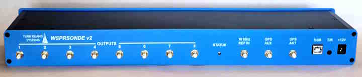
The WS-8 has new software available, with new features and a flexible method of dynamically changing modes, as well as other options. From the updated User’s Guide:
New Features (software version 2.3.2)
Two new features allow flexible control of the WS-8 operation:
Channel Modes: CHAN
Each output channel can be configured in one of three modes:
Beacon – This will be the globally-selected WSPR or FST4W-x modes.
CW – The channel will transmit a “Tone-Zero” signal for the duration of the scheduled channel transmit frames.
Fixed-frequency – The channel will transmit a continuous “Tone-Zero” signal.
Flexible Scheduling: CRON
This is a loose subset of the Linux “cron”, allowing any WS-8 command to be executed on a minute/hour schedule. This can be used to change any parameter option, including channel transmit schedules, frequencies, and modes.
These powerful options should be used with care, as much of the propagation research benefits from stable and consistent signals.
Both the new program and the user’s guide are available for download:
Over on my wb6cxc.com blog I have posted about SDR dynamic range and some related Turn Island Systems products that are in the early prototype stage: a Filter-Preamp with a 60 MHz antialias filter optimized for 88-108 MHz FM broadcast band rejection, and a completely new multiband receive filter-bank which (in many cases) will reduce MW and SW broadcast band overload . I hope to have these fine-tuned and available very soon!
I invite you to participate in the development discussion:
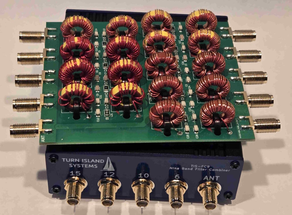
There are several prototype versions of the 9BFC in operation, and they work just fine when connected to a decent multiband antenna.
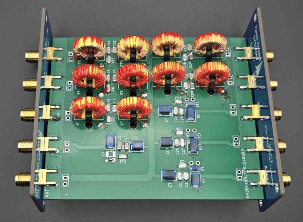
BUT – when connected to a high SWR antenna (as is sometimes necessary in the field) the internal surface mount inductors can get disturbingly warm. The prototype 9BFC used a mix of surface mount and toroid inductors.
So, I am announcing the brand new all-toroid version of the 9BFC!
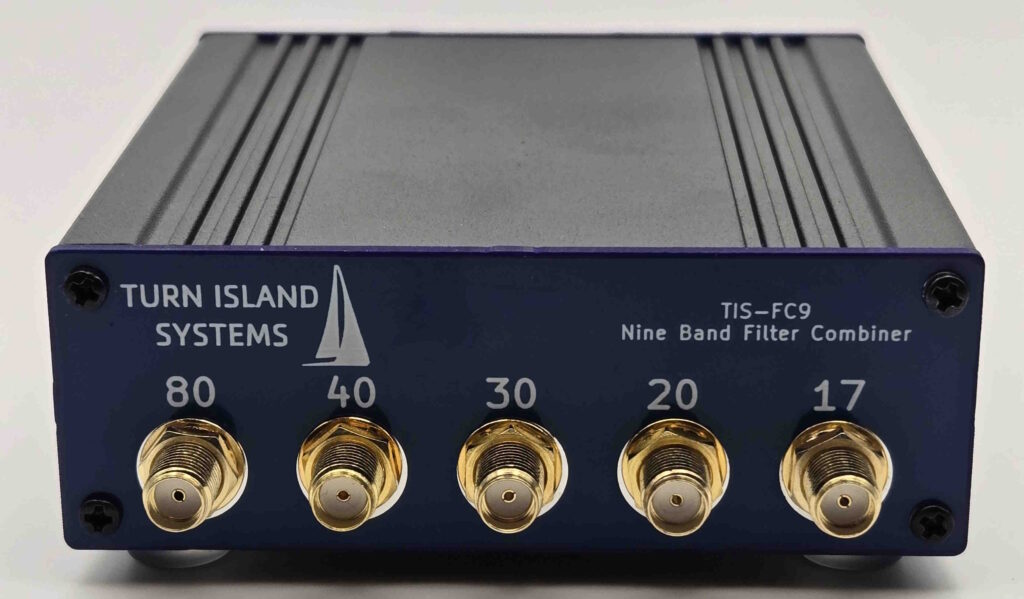
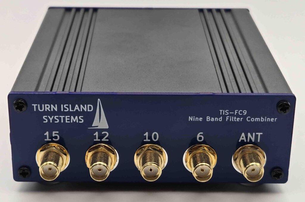
The 9BFC covers the 80, 40, 30, 20, 17, 15, 12, 10, 10 and 6-meter ham bands. This design has demonstrated its resilience and performance under all load conditions, and so has become the production version of the 9BFC.
I’ve been trying to avoid this one because winding and adjusting all those toroids is tedious and time-consuming, but this thing just makes so much sense that I had to do it. The Nine-Band Filter-Combiner (9BFC) is yet another filter-combiner for use with the WSPRSONDE and other QRP transmitters, and it allows a single multi-band antenna to be driven by multiple transmitters. It combines inputs on 80, 40, 30, 20, 17, 15, 12, 10, and 6 meter ham bands. You don’t have to use all the inputs; leaving any unused ones unconnected is just fine.
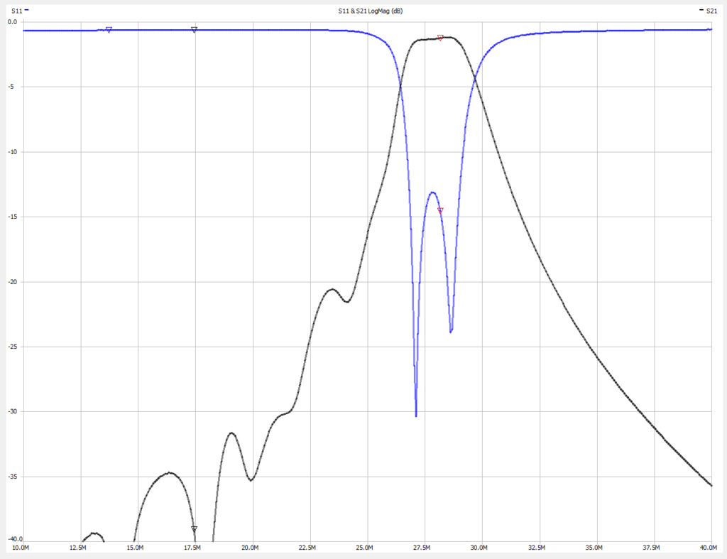
The 9BFC design is quite a bit more critical than the previous 6-band combiner, as the added 17 and 12 meter bands are extremely close to the 20, 15, and 10 meter bands. This tight spacing requires rather narrow filter passbands, and there is always a tradeoff between filter bandwidth, inductor “Q”, and filter loss. In order to keep the 9BFC loss to a reasonable level, commercially-available surface-mount inductors as used in the 6BFC are not adequate for these five closely-spaced bands. Instead, I am using iron-powder toroids (T50-6 variety) for those frequencies. The 80, 40, 30, and 6 meter filters do use surface-mount inductors.
Not only are these toroids tedious to wind, but the inductance of each of the ten toroids must be carefully adjusted to provide the proper filter shape and impedance match. Adjustment is done by spreading or compressing the windings while observing the filter response with a Vector Network Analyzer — this process requires some iteration since each channel has two toroids and they do interact. Once adjustments are complete the windings are secured with fingernail polish.
Of course, your antenna has to support the bands in use. When using the eight-output WSPRSONDE and the EFHW-8010 (end-fed half wave, 80-10 meters, from myantennas.com) I am using all the 9BFC inputs but the 6 meter port. It works quite well (my two WSPRSONDE locations are shown here, Friday Harbor WA, and Occidental CA). I have a separate 6-meter antenna for the Occidental site.