Test Results: Shelving / Low-Pass Filter

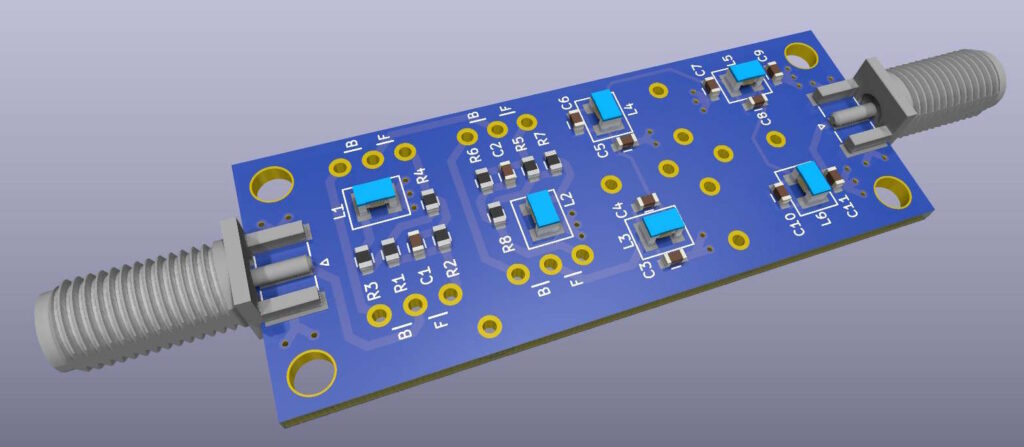
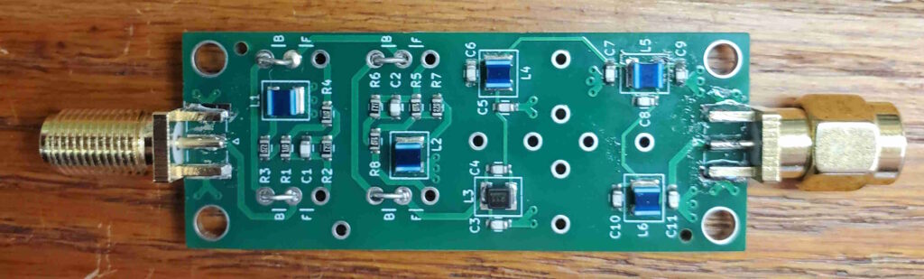
The assembled Shelving/LPF boards were delivered yesterday, and the “missing” inductor was delivered today (one inductor was not in stock at JLCPCB so I had then assemble it without that one part; I ordered that inductor from DigiKey). Amazingly fast service from JLCPCB! So I soldered on that inductor and the SMA connectors and did some testing:

This board has options where the shelving filter can be bypassed, so I tried that first. The results were much better than I had expected:

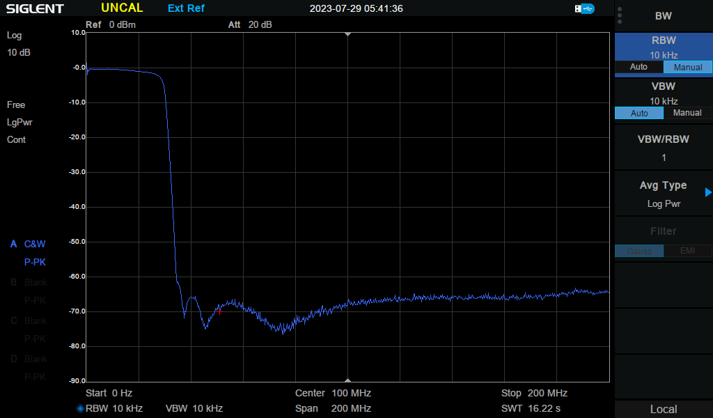
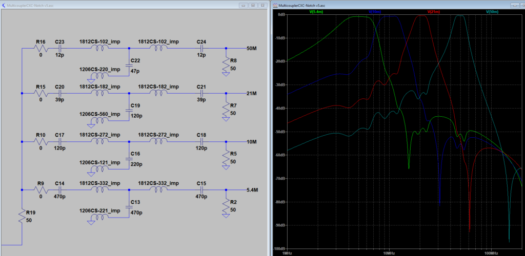
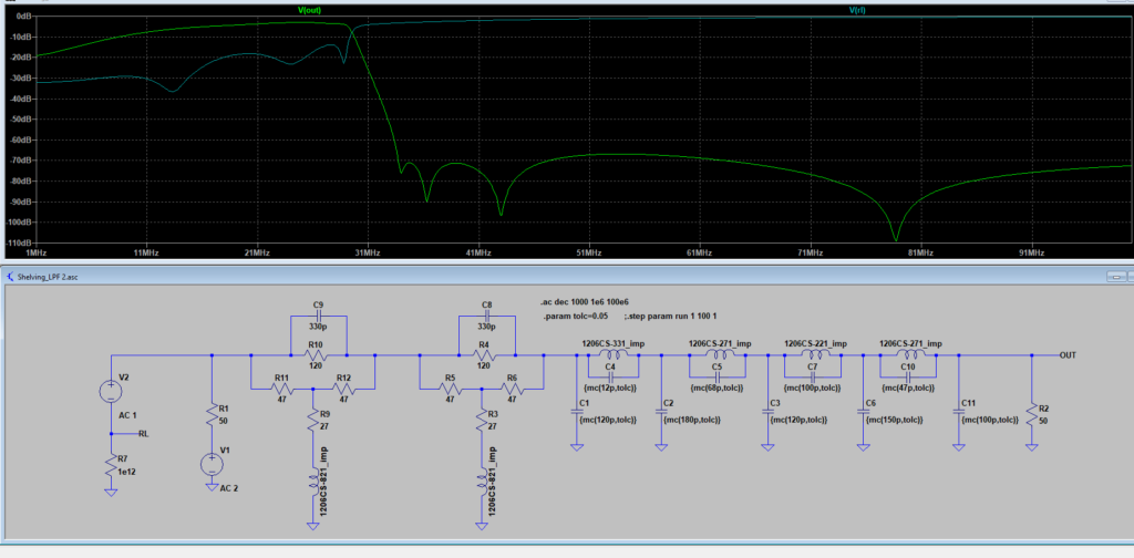
This essentially matches the performance of the LTSpice simulation (which used the Coilcraft inductor models, not the similar Murata inductors on the board. This shows a reasonably sharp rolloff with better than 60dB stopband attenuation. I am seeing no obvious inter-stage coupling (which can be a concern when using unshielded solenoid inductors.)

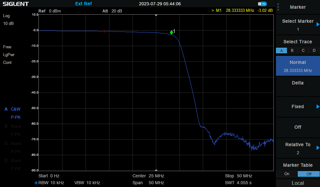
Here is a closer look at the roll-off performance. The loss at 1MHz is essentially zero, while the -3dB point is about 28 MHz. We may want to push this corner frequency a bit higher…

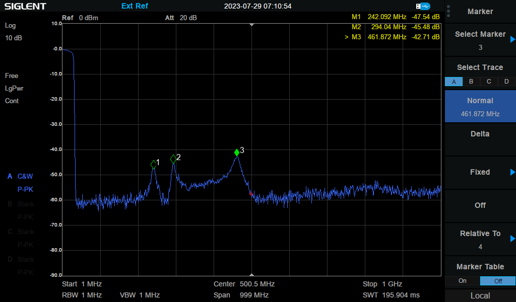
There are some spurious responses above 240 MHz. I suspect that these won’t be a problem because the SDRs that will be using these filters will already have an anti-aliasing filter that should adequately knock down these frequencies. I could guess that these come from inter-stage trace inductance, but that’s just a guess:

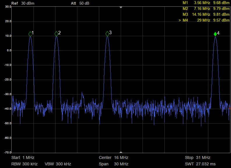
With the shelfing filters in place, the low-frequency attenuation is about 20dB:

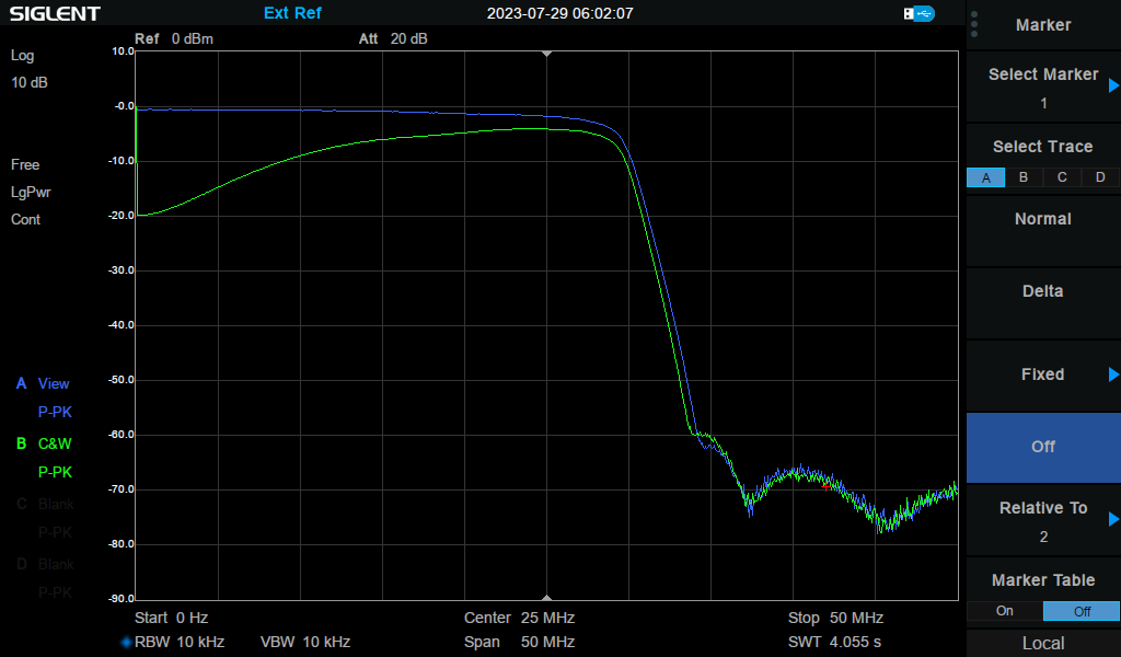
There is also extra attenuation above 25 MHz, which suggests that we shift the shelving mid-point frequency slightly lower to reduce higher-frequency attenuation.

In conclusion, I am quite pleased with the overall design and layout of this board. Tweaking the frequencies (if necessary) will be trivial.

Filters, Filters, and More Filters

When writing software loses its appeal I take a break and do something concrete — hardware design. Here are some recent filter designs:

Four-Band Filter/Combiner:

This is used to combine the 1W square-wave outputs of the BeaconBlaster, filtering out the bad harmonics and combining all four inputs into one output which will feed a multiband antenna. We wanted to make this unit with off-the-shelf surface-mount components, so we needed to design fairly wide filters, no closer than one octave apart or there would be excessive interaction between sections. The filter topology also needed to show a high off-channel impedance, again to avoid interactions. Available inductors limited the design to 1W power on each port, with less than 1dB of loss.

The image below shows a simulation of the 60/30/15/6-meter version of this filter. Note that each filter has a deep 3rd harmonic notch.

And here is the spectrum of the 80/40/20/10-meter filter, being driven by the BeaconBlaster (using a 20 dB attenuator, actual power levels about 1W per channel). You can see the 80 meter 3rd harmonic at -40dBc:

A Shelving / Low-Pass Filter

This board combines a two-stage 10 MHz shelving filter, and a steep four-section 30 MHz elliptic low-pass filter.  This is intended to go between an antenna and a SDR having a sample rate of 66 MHz.  The shelving filter attenuates the low-frequency signals (where SDR overload is typically a problem), and the LPF is for additional anti-aliasing.  The “ideal” design promises 70dB stopband attenuation, simulations show better than 60dB with available surface-mount inductors, and if I get at least 50dB then I will consider it a success.

Boards should be ready for testing in a couple of weeks.

This is being developed in collaboration with some folks who are running multiband receiver sites, including WebSDR and ionosphere research installations. In particular I should acknowledge the advice and contributions of Clint Turner (KA7OEI). The shelving filter was stolen directly from his website: https://ka7oei.blogspot.com/2020/08/revisiting-limited-attenuation-high.html

BeaconBlaster Progress

While waiting for more chassis to arrive I’ve been testing the first two prototypes and the results are excellent. Prototype #1 has been running in Friday Harbor for a few weeks, using the filter/combiners to feed two antennas. Both antennas are Off-Center-Feed dipoles (which provide good matching on octave-spaced bands, rather than the third-harmonic spacing of a center-fed dipole). One antenna is for 80/40/20/10 meters, and the other is for 30/15 meters. The one Watt signals on the six transmit frequencies have been received by every known FST4W-120 receiver on the planet:

Prototype #2 has also been running, using my site near Bodega Bay, California:

This one is driving a single OCF Dipole designed for 40/20/10 meters. I am also connecting an 80 meter transmit channel to this antenna — a *very* lousy match, but it is still being received far and wide. You may be wondering about the module sitting on the saucer; rather than use a GPSDO at this location I decided to use a cheap surplus 10 MHz OCXO for the reference clock. You can also see the four-band filter/combiner connected between the BeaconBlaster and the SWR meter (and then the antenna). Here’s a typical day’s propagation for this one:

These propagation charts may not look very impressive when you compare them do typical WSPR reports, but remember, there are actually very few FST4W receiver sites in operation. Work is being done to upgrade WSPR signal monitoring software, but for now FST4W is really the only game in town for collecting accurate Doppler spreading data needed for atmospheric propagation research. Anticipating upcoming WSPR upgrades, the BeaconBlaster will be WSPR-capable very soon.

So progress is being made. Enough subassembly boards are available to build a few more units, and more boards are on the way. The new chassis should look a bit more professional as well. Full details will be coming soon (I promise!)