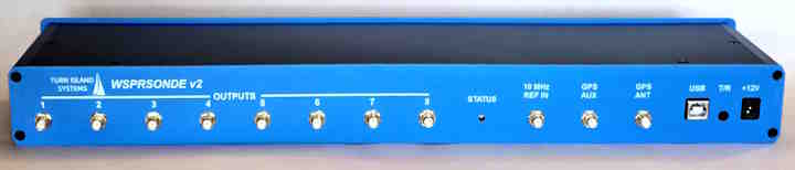
Here is an opportunity to help in the exciting field of ionospheric propagation and other “space weather” research, by hosting a WSPRSONDE system provided by the HamSCI organization. HamSci is looking for a few good sites in North America for these WSPR / FST4W research transmitters. There are already about a dozen of these situated in various locations and HamSCI is looking forward to filling in some of the gaps.
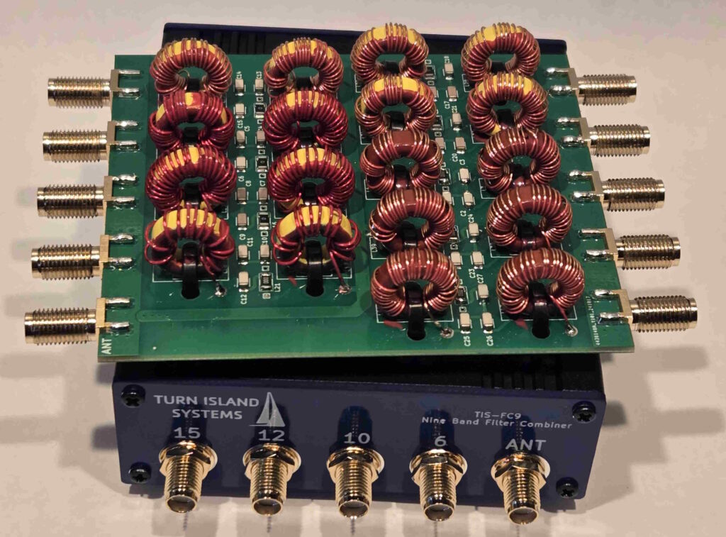
The HamSCI package will include the WSPRSONDE, a 9-Band Filter-Combiner, a Bodnar GPSDO, an 80-10 meter end-fed halfwave antenna, power supplies, and all necessary cabling. You will provide a good home for this gear.
If you are interested, visit the HamSCI website for this project:
https://hamsci.org/wsprsonde-psws-transmitter
Turn Island Systems in QST!
(Well, one of our Filter-Combiners is in a group photo anyway…)
The July 2025 issue of QST contains a great article about reducing the noise from local sources and optimizing WSPR reception, written by Conrad Trautmann (N2YCH) . Conrad is a friend, and a regular contributor to the wsprdaemon community. The TIS Filter-Combiner is shown among a collection of WSPR gear.