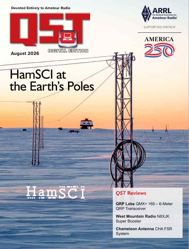
The August 2026 QST features some great material about HamSCI, including some nice mentions of Turn Island Systems gear and a brief section (written by me) highlighting the Time Of Flight measurement developments from Turn Island Systems and others.
The cover photo is of the Neumayer Station III in Antarctica, which hosts SDR receivers running wsprdaemon, and also a TIS WSPRsonde 8-channel transmitter.
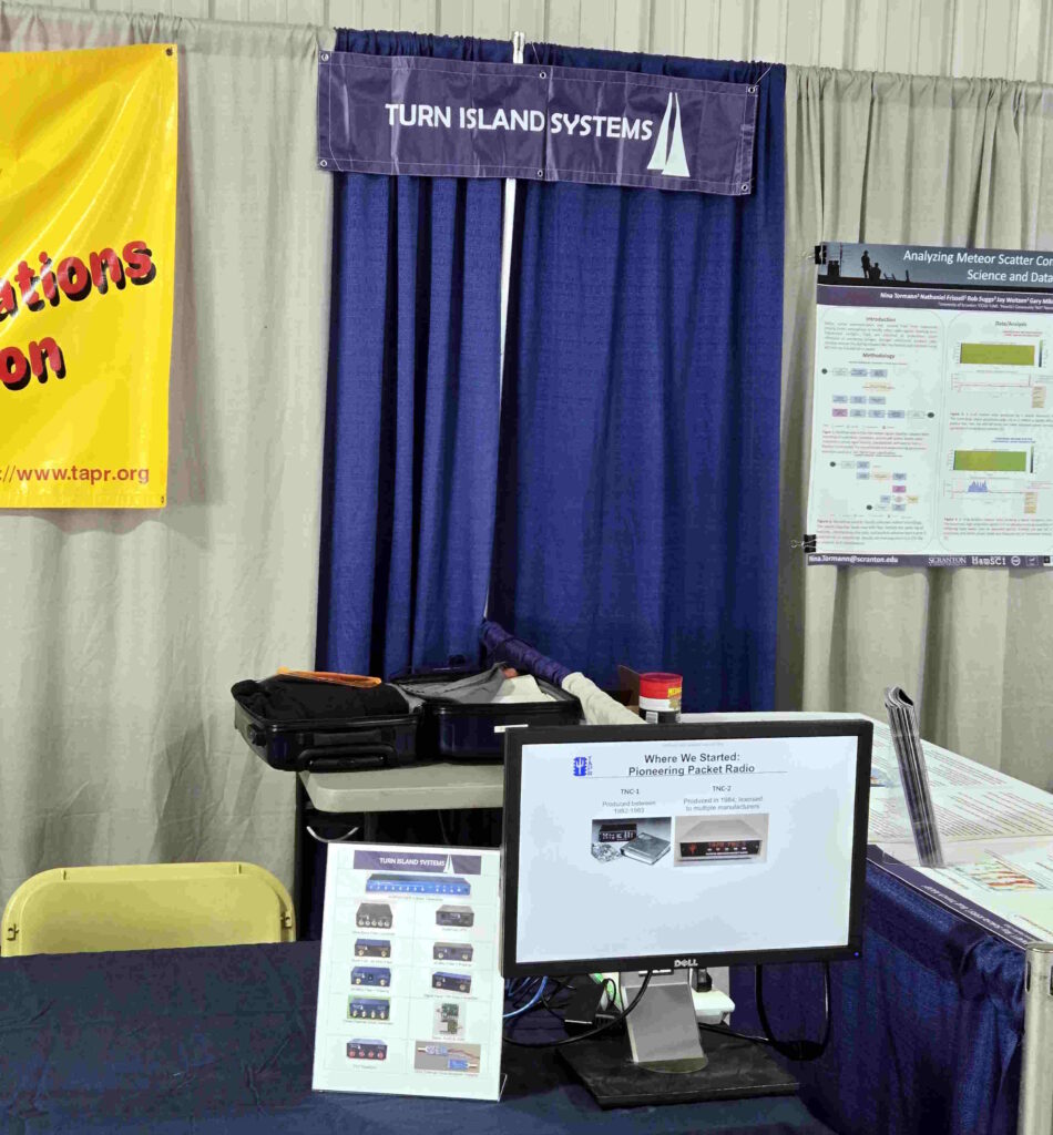
I was wearing three hats at the 2026 Dayton Hamvention (actually in Xenia, OH): Turn Island Systems, TAPR, and HamSCI– a very busy weekend. So busy that I only took this one picture (we were just beginning to set up):
Lots of folks stopped by to see what we had going on, to ask questions, and to just chat. My voice dropped one octave over the course of the event and I enjoyed every minute of it!
On Friday TAPR held a lecture session and I gave a presentation on the Time of Flight work being done using tools from Turn Island Systems, TAPR, wsprdaemon, and HamSCI. Also in my presentation was a brief introduction to a new SDR receiver, based on the RX-888, we are doing at TAPR. Video of my presentation may surface some day, but here are the slides from it:
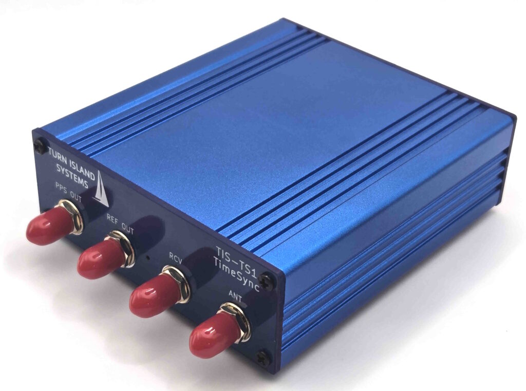
By the way, the TIS-TS1 TimeSync I’ve been working on and describing here is now available for sale. The prototypes have been deployed and tested with good results, and production run units look great. It’s pretty specialized, but if you need one you can now get it here on the TIS website:
Here is my Time of Flight presentation, where I describe the addition of the time domain to the suite of precision measurements delivered by the wsprdaemon system. The following two videos are of the same presentation (because I like redundancy for fault-tolerance):
Discussing the TAPRX-888 SDR design — This is a TAPR project that I am working on, creating the schematic and layout package for a true open-source SDR:
Upcoming: Hamvention 2026 — I will be presenting an update on the Time of Flight systems, including details on the implementation of a time-stamped transmit beacon. If you miss the presentation, please stop the TAPR and HamSCI tables and say hello!
Here’s a preview of a product in development, designed to add Time of Arrival and Time of Flight measurement capability to the RX-888 SDR as used in the wsprdaemon network:
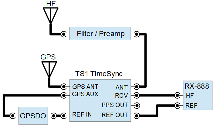
Yes, it’s another Blue Box from Turn Island Systems. This “TS1” generates a carrier signal modulated by the Pulse per Second output of a GPS receiver module, and sends it to the HF input of the RX-888:
With the TS1 and using an enhanced version of ka9q-radio software we have been able to measure the Time of Arrival of (for example) WWV transmissions with microsecond accuracy. A prototype of this unit has been running at the Boulder Colorado WW0WWV site (located on the grounds of the WWV transmitters), and the version shown above at the KPH receiver site on the Point Reyes peninsula in northern California.
We expect that this new measurement capability will be very useful in the development and evaluation of propagation models.
This is a work in progress, but look here if you would like to see some early documentation:
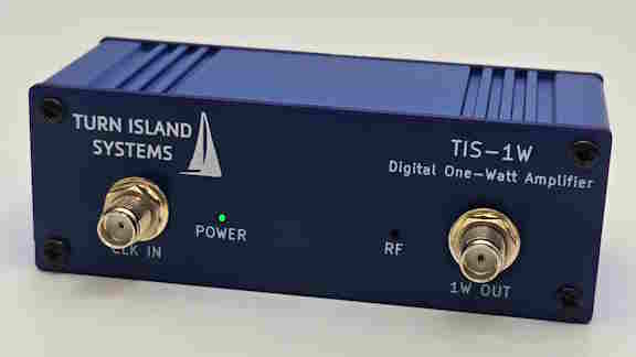
Turn your logic-level outputs into slightly more powerful signals! This design is one I have been using in the WSPRSONDE, and I’ve found it to be so useful that I put it in a little box along with a USB C power connection and a couple of indicator LEDs.
This will require a low-pass filter to convert the square wave output to a spectrally-pure-meets-all-FCC-regulations signal, but that’s pretty simple. This design easily covers all the ham bands between 160 and 6 meters.
Equipment using this amplifier circuit has been continuously transmitting for several years, from the steamy jungles of Costa Rica to the frozen wastes of the Arctic and Antarctic, The design and performance is thoroughly described in the product guide.
We’ve seen that that the small computers used in wsprsonde (and other) receive installations will reset or hang up during power outages, even when there is a UPS between the utility power and the computer’s power brick. It turns out that many UPS units have a momentary dropout when they transition to backup mode, and the brick power supplies do not have enough internal storage to ride through this transition. This is bad enough in home operation, but especially problematic in a remote installation with limited access.
There are certainly glitchless UPS products available (“on-line” UPS), but these are more expensive and sometimes “glitchless” really isn’t.
The TIS-1250 provides an alternative solution, by using a “supercapacitor” (1.25 Farads) and low-loss charging / discharging circuitry.
The TIS-B1 Balun converts a 50 Ohm signal to a balanced 100 Ohm impedance as needed when using twisted-pair CAT 5 and CAT 6 ethernet cable.
Ethernet cable is being used in advanced balanced wideband “probe” receive antenna systems, where balance and ground isolation is extremely useful in reducing common-mode interference. The TIS-B1 Balun can be very useful in developing and testing these antenna systems.
For more information, please see the Users Guide: TIS-B1.pdf
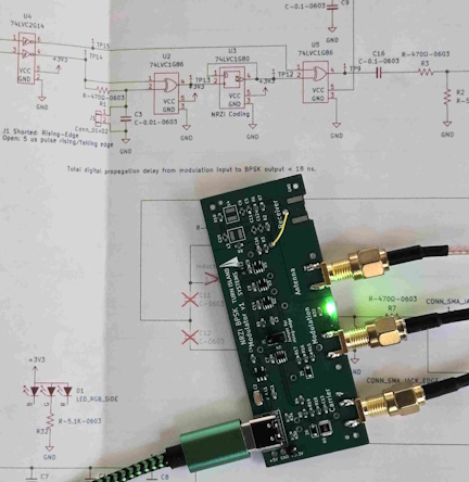
I have a new post on my ham blog showing a potential Turn Island product, and how I use the TIS-126 Clock Distribution Buffer and the TIS-5351 TinyClock to solve some test-setup problems:
The new design is a BPSK modulator to be used to generate an in-band time-sync signal. This signal is injected into the antenna port of a receiver and used in time-of-flight and time-of-reception measurements.
The BPSK modulator can also be used to generate over-the-air signals using NRZI BPSK modulation . I show some test results in the blog.