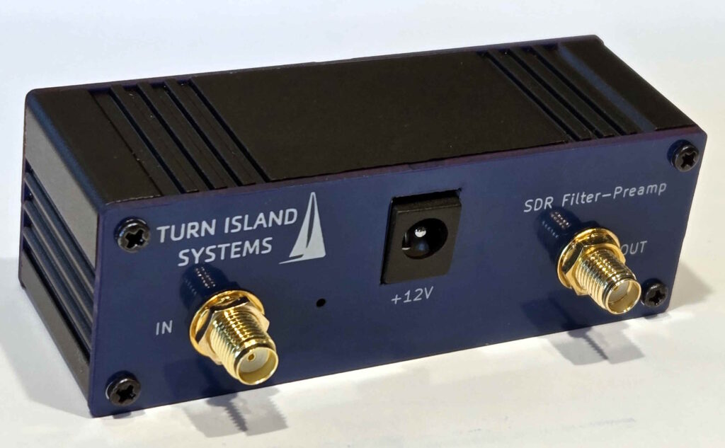
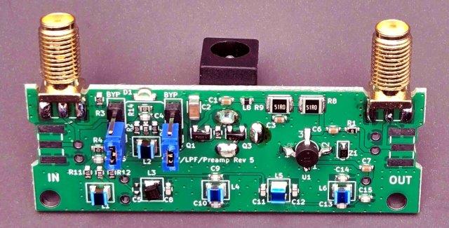
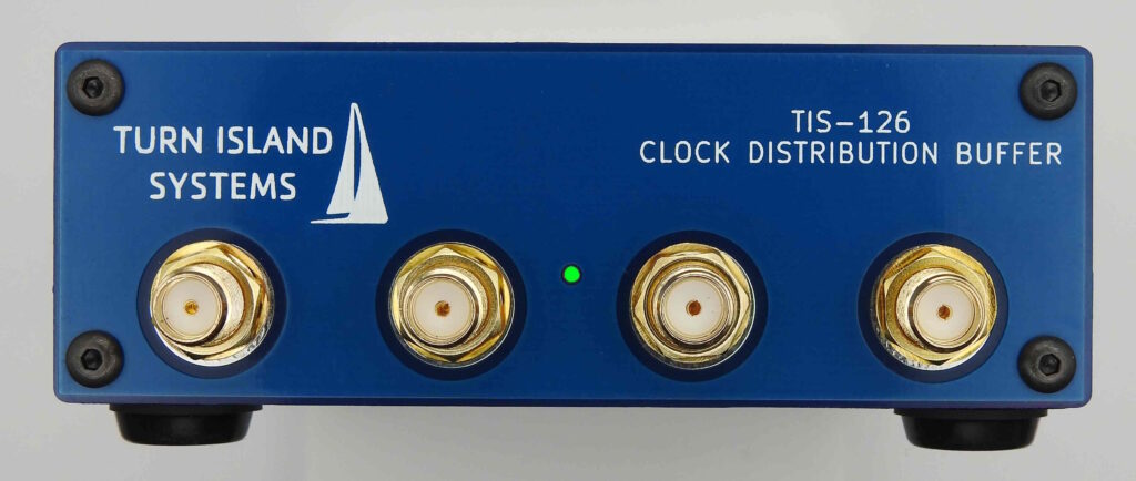
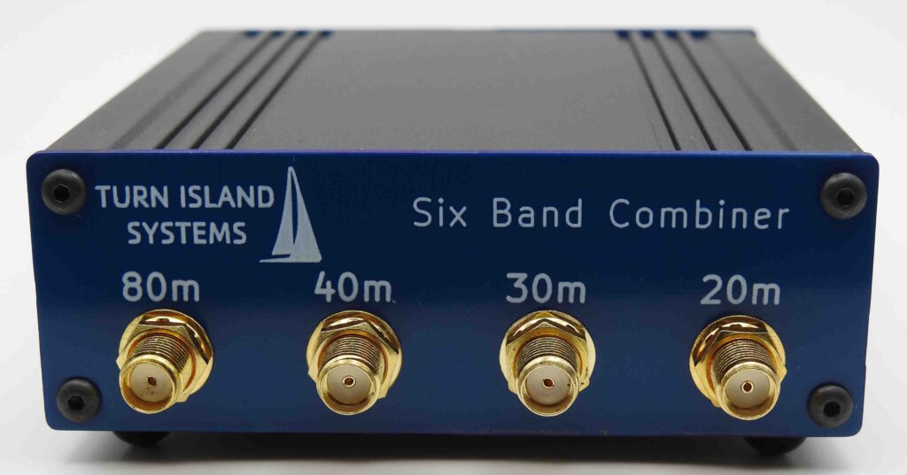
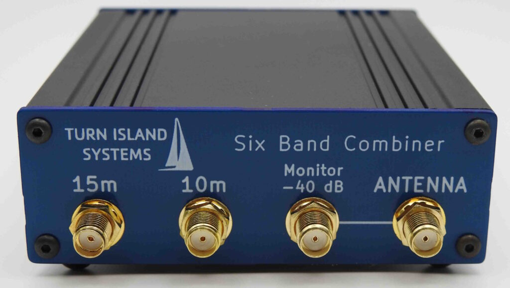
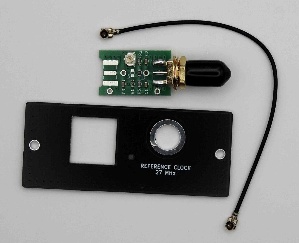
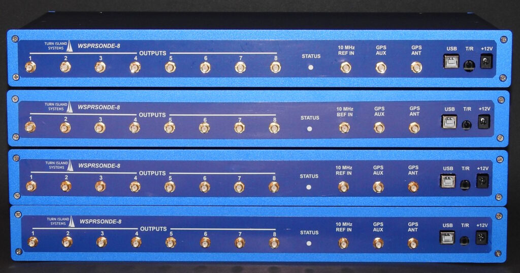
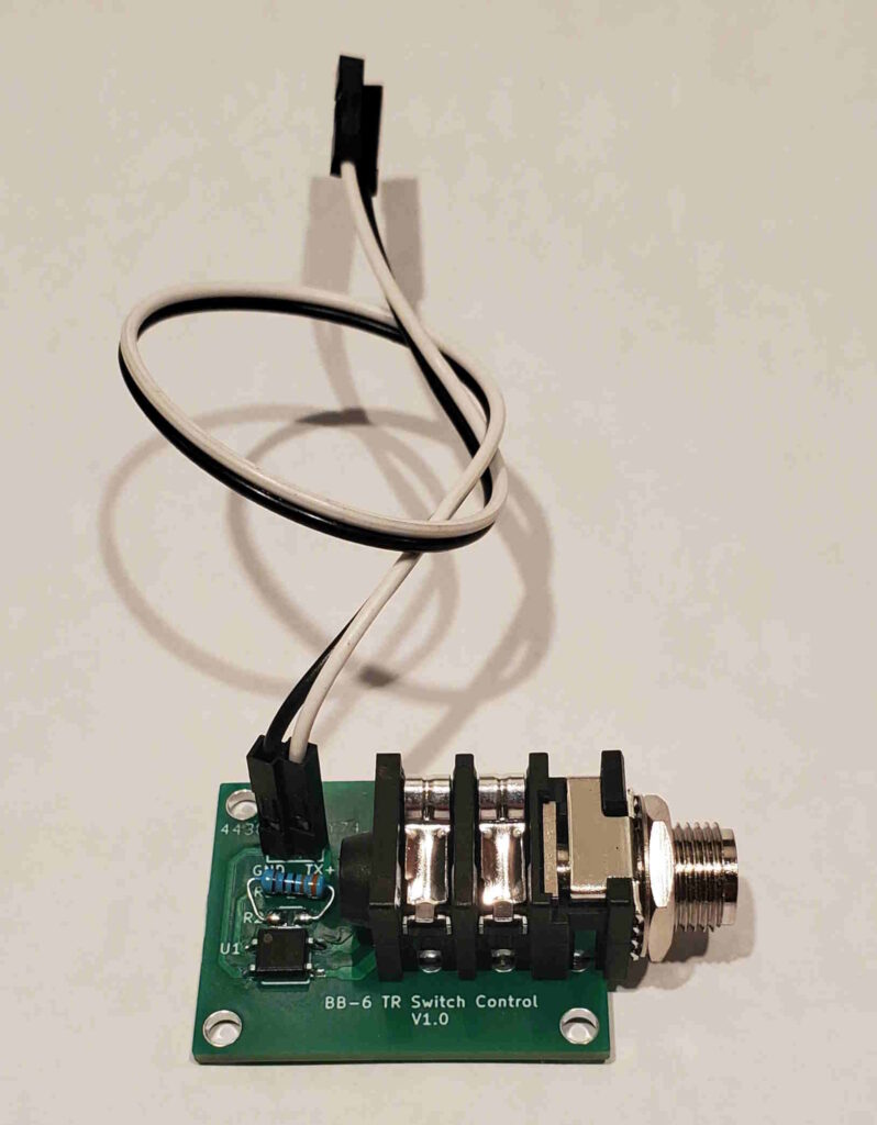
Five units are ready to go (four of them shown here).
All posts by admin
BB-6 T/R Switch Interface
If the Beacon Blaster 6 is to be used with a receiver on a shared antenna, an external Transmit/Receive switch will be required. Some T/R switches provide automatic sensing that switches modes when the transmitter starts. This can work well, especially given the relatively low-power output of the BB-6.
But there are advantages to an externally-controlled switch, usually driven by the “PTT” output of the transmitter (this is often an “RCA” or phono jack.) This output is generally a contact-closure (relay or transistor) to ground, which connects during transmit.
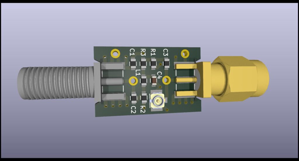
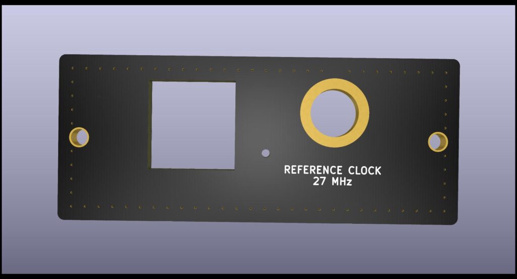
The BB-6 T/R Switch Interface provides this control signal. Installation will require that a 10mm (or 3/8”) hole be drilled in the BB-6 rear panel, and the attached control wires be plugged onto an existing header on the BB-6 control board.
BB-6 firmware version 2.4.0 or later is required.
The T/R Switch Interface is offered free of charge to all owners of the BB-6, so please let me know if you want one.
More details here:
https://turnislandsystems.com/wp-content/uploads/2024/01/BB6-TRS.pdf
(the image above shows a 1/4W resistor where a small surface-mount resistor should be. Turns out I didn’t have the proper value on-hand when building the test unit.)
WSPRSONDE-8
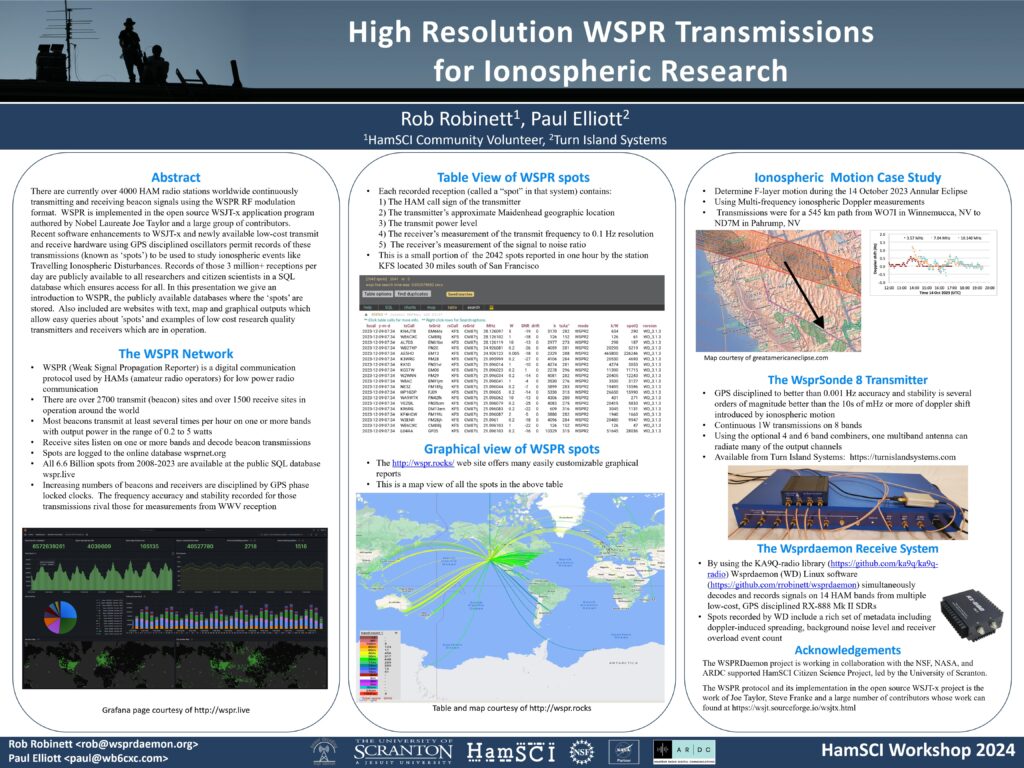
Announcing the next stage in Beacon Blaster evolution: The WSPRSONDE 8!
This is still in development, but the initial prototypes look very promising. Similar in many ways to the BB-6, this has the same type of frequency-flexible 1W Digital (square wave) outputs, the same GPS and 10 MHz clock reference inputs, 9-24VDC input, and USB configuration port. The WSPRSONDE-8 supports both WSPR and FST4W-120 modes.
But the WSPRSONDE-8 adds these new features:
- Eight frequency-flexible outputs, 1W, 160-6 meters (requires external filtering)
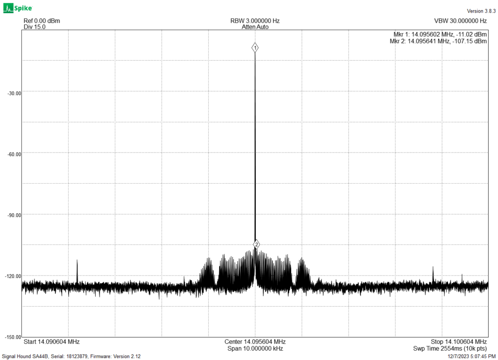
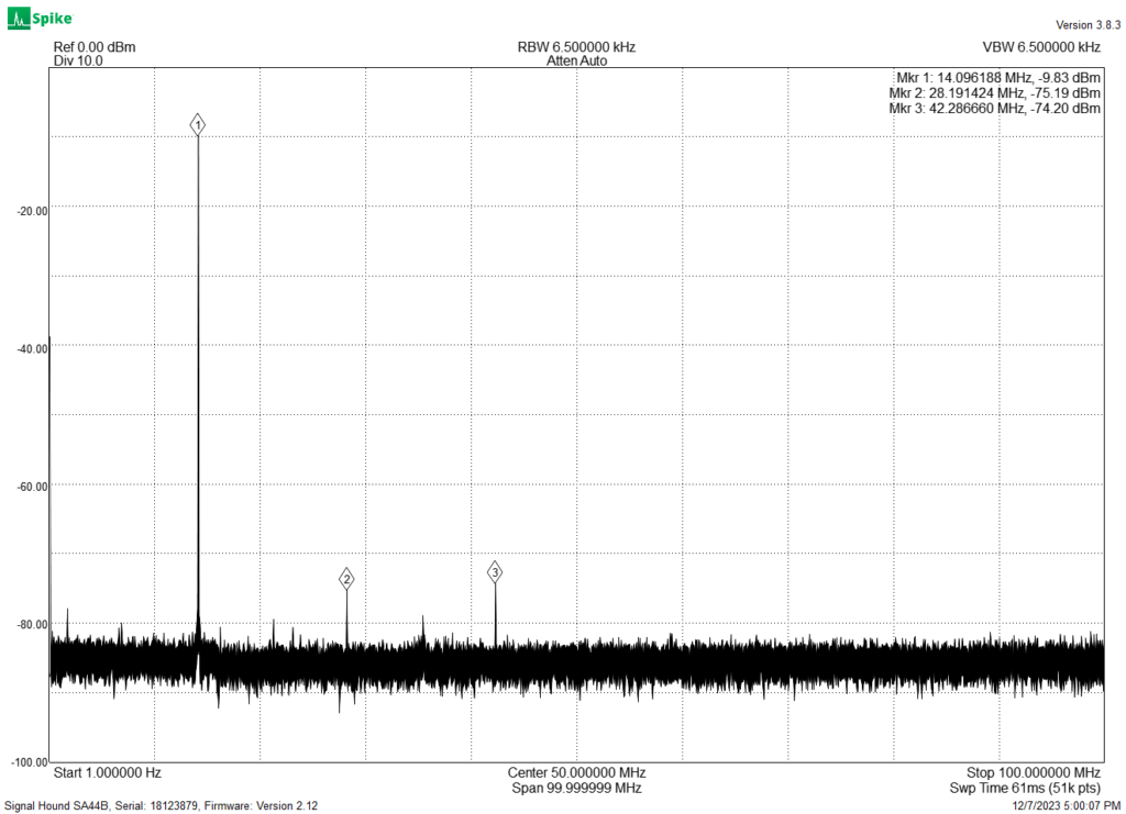
- Spurious output levels greatly reduced. The BB-6 was designed to meet a spurious output level of -40dBc or better. The WSPRSONDE-8 uses a different modulation technique to provide close-in spurs typically better than -90dBc
- A single-board design that eliminates the many subassemblies and interconnections inside the BB-6. This is a rugged system.
The WSPRSOND-8 provides ultimate frequency accuracy and stability limited only by the external 10 MHz reference.
Beacon Blaster 6 Now Supports WSPR
I’ve been running this code (or the previous version) for a few weeks now, and it runs well. The latest version of wsprdaemon is able to calculate spectral spreading for WSPR as well as FST4W, so there’s little reason not to switch over to WSPR.
There are some upgrades to the configuration commands and I will be soon editing the user’s guide to show this, but the old commands still work: just add “MODE WSPR” to the start of your config.txt file. Then reload the file (or restart the BB-6) and you’re now running WSPR!
Get the new Version 2.3.1 upload here:
Eclipse!
We’ve had at least five Beacon Blaster 6 boxes running during last week’s solar eclipse (plus another custom beacon design that used the BB-6 motherboard.) A lot of good propagation data was captured using these and other beacons.
I’ve got two BB-6 prototypes running, one in Friday Harbor Washington (WB6CXC, Grid CN88) and another in Occidental California (WB6CXC, Grid CM88). These were both transmitting on 80, 40, 30, 20, 15, and 10 meters, connected through a prototype Six-Band Filter/Combiner.
Here’s the setup in Occidental:
Prior to the eclipse, in order to verify the BB-6 “baseline” performance I set up a little monitoring system. This way we can confirm the validity of remote measurements of frequency, amplitude, or spread.
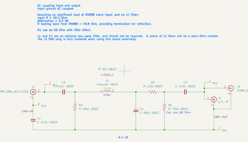
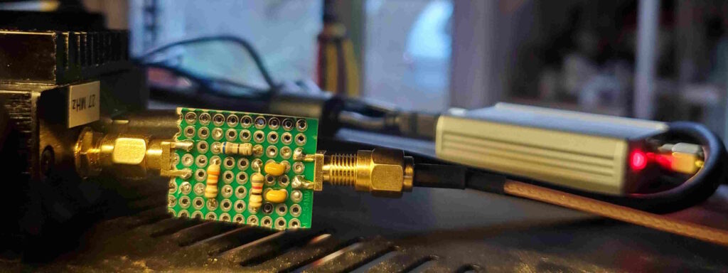
To do this I used a QRP-Labs “QDX” transceiver, running as a receiver on the 20 meter band. Some external shielding and cable-clamp chokes were needed to attenuate the strong local signal, as even with a dummy-load in the QDX antenna jack the receiver was initially overloading. The QDX was then connected to a computer running the wsjtx program to decode my FST4W-120 transmissions. wsjtx saves a log file showing the time-stamped parameters of every decoded transmission.
For additional monitoring the “-40 dB Tap” output of the Combiner was connected to a spectrum analyzer, which was also plugged into the computer. I first used a “SignalHound SA-44B” analyzer, but wanting to free up that device for other measurements I switched to the amazing “tinySA” (which also has an available computer interface program.)
The Bodnar GPSDO which provides the 10 MHz clock to both the BB-6 and the QDX has a monitoring program that displays internal PLL and GPS satellite status — this was also on the screen.
Finally, the BB-6 USB serial port was connected to the “Putty” terminal emulator. Here’s how it looked:
Here’s the tinySA in action:
The BB-6 performed flawlessly!
Beacon Blaster 6 errata
My apologies, but the help file for the “Schedule” command is in error. Here is the corrected one:
Schedule [channel] [transmit slot] [sequence length] ([morse ID interval])
channel: 1-6
transmit slot : transmit on slot #
sequence length : repeat every # timeslots
morse ID interval : send morse ID rather than beacon every # transmissions.
Examples:
Sched 1 1 1 : channel 1, transmit every timeslot.
Sched 1 1 2 : channel 1, transmit every two timeslots, starting with timeslot 1.
Sched 6 3 3 : channel 6, transmit every three timeslots, starting with timeslot 3.
Sched 4 1 1 5 : channel 4, transmit every timeslot, sending morse message every five transmissions.
BB-6 goes to Antarctica!
The first build of the Beacon Blaster 6 transmitters is being deployed, and I am very excited to announce that one of these is on the way to the remote Neumayer Station III in Antarctica.
Some of the researchers there are radio amateurs and have been operating from this remote location using WSPR and other modes. The BB-6 will provide FST4W capability, and the frequency stability and “spreading” resolution of this mode (and this polar location) will greatly enhance the ability to study ionospheric propagation. Neumayer Station III operates under the callsign DP0GVN.
Neumayer Station III is operated by the Alfred Wegener institute, which is a center for polar and marine research, with particular focus on the cold and temperate regions of the world.
The Alfred Wegener institute is not limited to this one Antarctic base — for more information please see:
https://www.awi.de/en/about-us.html
https://www.awi.de/en/expedition.html
https://www.awi.de/en/expedition/stations/neumayer-station-iii.html
Of particular amateur radio interest, the Alfred Wegener institute ship Polarstern was very recently operating in the vicinity of the North Pole, and has been transmitting WSPR, call sign DP0POL:
https://follow-polarstern.awi.de/?lang=en#main-menu
Beacon Blaster 6 User’s Guide and other downloads available
Check out the new Downloads page!
Evolution of the Beacon Blaster 6
The photo below shows the evolution of the BB-6 from proto #1 (bottom) to the final design (top):
The top unit uses the full-size label (created on Steve’s large-format printer), and the faceplate as carved by my CNC mill. I am now in the process of assembling a few more Beacon Blaster 6 units, and should have them ready to go within a week.
Yet Another Filter: Seven Band Combiner
While the four-channel filter-combiner is a practical accessory for the Beacon Blaster 6, it is becoming obvious that another filter-combiner will be useful. The 4-channel unit uses standard surface-mount inductors, and the inductor Q and current specs mean that for low-loss the filters need to be fairly wide, spaced at least one octave apart.
But if you have an antenna capable of working on more bands (such as the Hy-Gain AV-680), a combiner with more channels would be nice. So, here is the Seven-Band Filter-Combiner:
This design uses custom-wound toroid core inductors, which allows much narrower low-loss filters. The board is designed to allow the inclusion of a third-harmonic notch for each channel, but the narrower filter bandwidth provides better than -40dB attenuation of all harmonics so the notch will likely not be needed.
Here is the 10 MHz filter with and without the notch:
This plot shows the 7-band filter response without the notch:
This board has been sent out for fab and assembly, once it shows up I will wind and solder the toroids (and connectors), and find out of reality matches my simulations. My track record in this regard has been pretty good, so I am optimistic.
This will be a more expensive filter than the 4-channel one — hand-wound toroids are quite labor-intensive. But if it eliminates the need for a second antenna…