Here’s a talk I gave at the Hamvention TAPR Forum on Friday. The first half is about SDRs: dynamic range, signal to noise optimization, filtering, sampling and aliasing, etc. Then I share some details about the WSPRSONDE. I enjoyed presenting this to a (surprisingly) full room.
In partnership with TAPR and HamSCI, Turn Island Systems will be going to next week’s Dayton Hamvention. On Friday I will be giving a TAPR Forum presentation covering the topics:
Optimizing wide-band SDR receiver performance
Development of a multi-channel research transmitter
(At the moment, the Hamvention website forum details are wrong, we are working on getting this fixed.)
Look for the TAPR and HamSCI tables in Building 5 (Hertz). I will be flying the Turn Island Systems banner there, and will be bringing a bunch of Turn Island Systems products for show and tell.
Just a note: Most of my circuit boards are fabbed and assembled in China. My semi-custom aluminum enclosures are also made in China. Recent orders are being charged a 175% import tariff and this will definitely affect the prices I need to charge in order to not lose money.
I am not increasing the prices for currently in-stock items.
The WS-8 has new software available, with new features and a flexible method of dynamically changing modes, as well as other options. From the updated User’s Guide:
New Features (software version 2.3.2)
Two new features allow flexible control of the WS-8 operation:
Channel Modes: CHAN
Each output channel can be configured in one of three modes:
Beacon – This will be the globally-selected WSPR or FST4W-x modes.
CW – The channel will transmit a “Tone-Zero” signal for the duration of the scheduled channel transmit frames.
Fixed-frequency – The channel will transmit a continuous “Tone-Zero” signal.
Flexible Scheduling: CRON
This is a loose subset of the Linux “cron”, allowing any WS-8 command to be executed on a minute/hour schedule. This can be used to change any parameter option, including channel transmit schedules, frequencies, and modes.
These powerful options should be used with care, as much of the propagation research benefits from stable and consistent signals.
Both the new program and the user’s guide are available for download:
Over on my wb6cxc.com blog I have posted about SDR dynamic range and some related Turn Island Systems products that are in the early prototype stage: a Filter-Preamp with a 60 MHz antialias filter optimized for 88-108 MHz FM broadcast band rejection, and a completely new multiband receive filter-bank which (in many cases) will reduce MW and SW broadcast band overload . I hope to have these fine-tuned and available very soon!
I invite you to participate in the development discussion:
There are several prototype versions of the 9BFC in operation, and they work just fine when connected to a decent multiband antenna.
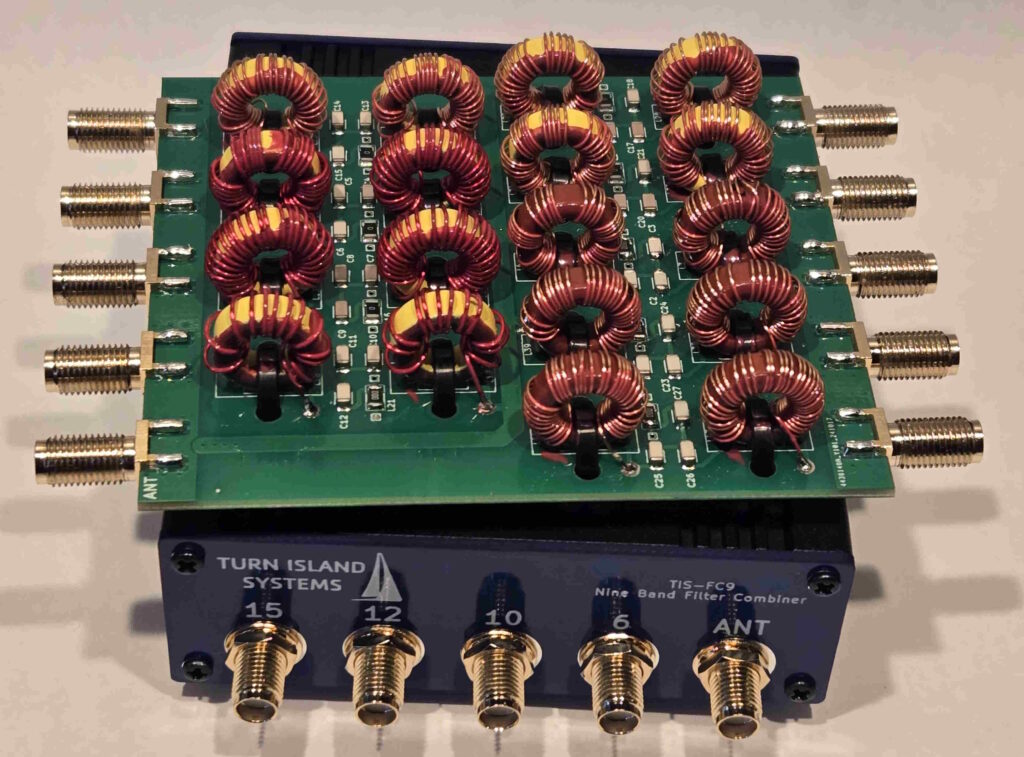
BUT – when connected to a high SWR antenna (as is sometimes necessary in the field) the internal surface mount inductors can get disturbingly warm. The prototype 9BFC used a mix of surface mount and toroid inductors.
So, I am announcing the brand new all-toroid version of the 9BFC!
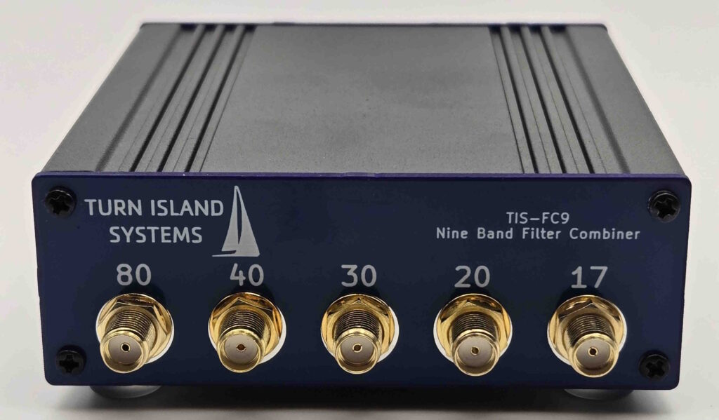
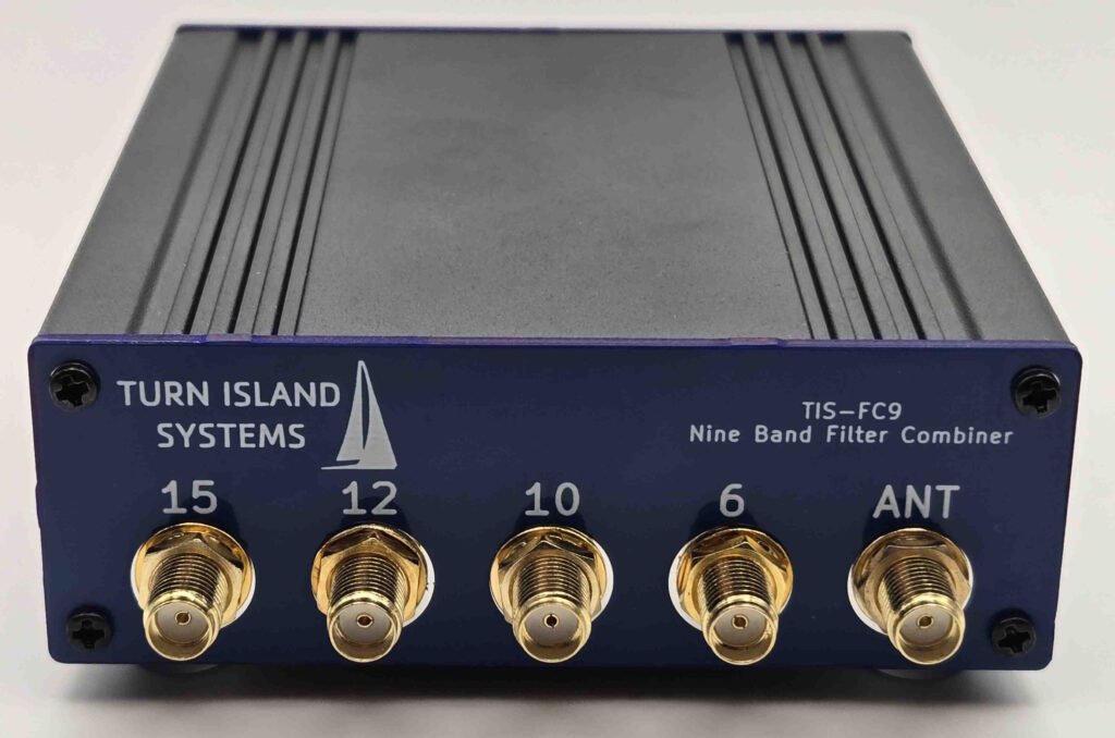
The 9BFC covers the 80, 40, 30, 20, 17, 15, 12, 10, 10 and 6-meter ham bands. This design has demonstrated its resilience and performance under all load conditions, and so has become the production version of the 9BFC.
I have added the Turn Island Systems “Product Satisfaction Policy” to our “About” page. This has always been our intent, so here it is in writing:
If you purchase a Turn Island Systems product and you are not happy with it for any reason (excluding obvious damage or abuse), return it to us and we will refund the purchase price less our shipping and sales tax costs. Even if the product works as specified, if it does not meet your needs you are welcome to return it for the refund.
“Any reason” means just that. For example, if it turns out that a preamplifier or filter doesn’t actually help your system performance (which can sometimes be tricky to determine), or you for any reason decide you don’t want it, feel free to return it.
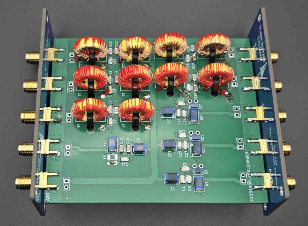
I’ve been trying to avoid this one because winding and adjusting all those toroids is tedious and time-consuming, but this thing just makes so much sense that I had to do it. The Nine-Band Filter-Combiner (9BFC) is yet another filter-combiner for use with the WSPRSONDE and other QRP transmitters, and it allows a single multi-band antenna to be driven by multiple transmitters. It combines inputs on 80, 40, 30, 20, 17, 15, 12, 10, and 6 meter ham bands. You don’t have to use all the inputs; leaving any unused ones unconnected is just fine.
The 9BFC design is quite a bit more critical than the previous 6-band combiner, as the added 17 and 12 meter bands are extremely close to the 20, 15, and 10 meter bands. This tight spacing requires rather narrow filter passbands, and there is always a tradeoff between filter bandwidth, inductor “Q”, and filter loss. In order to keep the 9BFC loss to a reasonable level, commercially-available surface-mount inductors as used in the 6BFC are not adequate for these five closely-spaced bands. Instead, I am using iron-powder toroids (T50-6 variety) for those frequencies. The 80, 40, 30, and 6 meter filters do use surface-mount inductors.
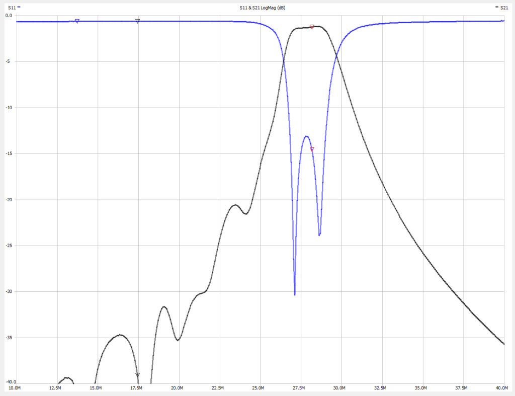
Not only are these toroids tedious to wind, but the inductance of each of the ten toroids must be carefully adjusted to provide the proper filter shape and impedance match. Adjustment is done by spreading or compressing the windings while observing the filter response with a Vector Network Analyzer — this process requires some iteration since each channel has two toroids and they do interact. Once adjustments are complete the windings are secured with fingernail polish.
Of course, your antenna has to support the bands in use. When using the eight-output WSPRSONDE and the EFHW-8010 (end-fed half wave, 80-10 meters, from myantennas.com) I am using all the 9BFC inputs but the 6 meter port. It works quite well (my two WSPRSONDE locations are shown here, Friday Harbor WA, and Occidental CA). I have a separate 6-meter antenna for the Occidental site.
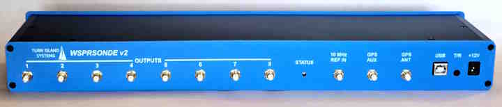
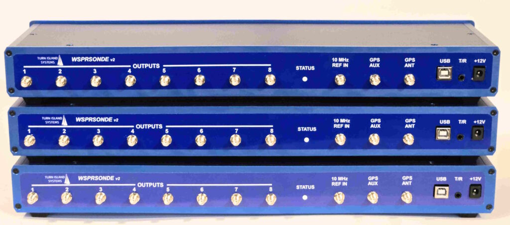
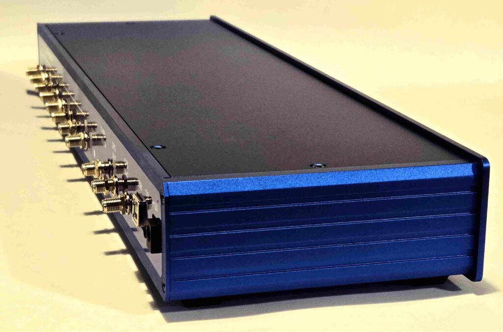
It’s alive!!! The new WSPRSONDE v2 WSPR/FST4W multichannel transmitters are rolling off the Turn Island Systems assembly line:
There are a few changes from the previous batch of WSPRSONDEs:
Smaller chassis, customized for Turn Island Systems.
Software control of output power: 1W or 250mW
There are a few other minor changes on the circuit board — things like Board Revision ID, allowing for future forward and backward compatibility.
But the WS-v2 is otherwise identical to the units that have been deployed on at least 2-1/2 continents. It continues to generate the clean, precise, and stable signals so necessary for accurate measurement of ionospheric propagation effects.
Along with this new hardware release comes updated WS firmware, with new features and options.
This has been in the works for a while now, and I am very pleased with the finished product!
If you are interested in some details of the WS-v2 assembly process, here is a short video of the Turn Island Systems CNC mill preparing a blank aluminum faceplate for the WS.
The forum has been quiet for some time, but it’s a good place to make comments, suggestions, critiques, and anything else even slightly related to Turn Island Systems.
And if you have one of our RX-888 Clock Adaptors (now available from TAPR), please share your experience with it — good or bad.